|
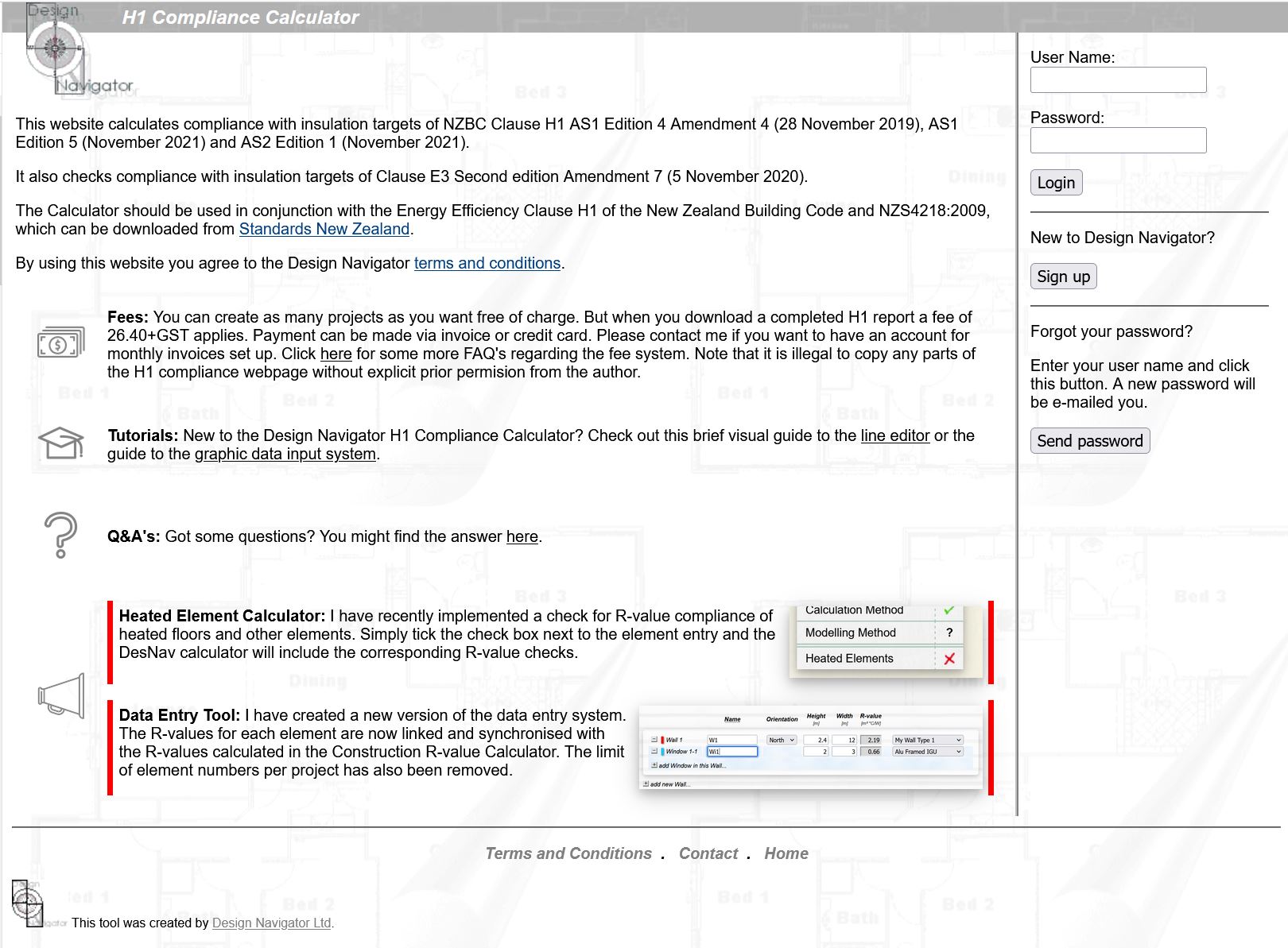
This website calculates compliance with insulation targets of NZBC Clause H1 AS1 Edition 4 Amendment 4 (28 November 2019), AS1 Edition 5 Amendment 1 (August 2022) and AS2 Edition 1 Amendment 1 (August 2022). It also checks compliance with insulation targets of Clause E3 Second edition Amendment 7 (5 November 2020). The Calculator should be used in conjunction with the Energy Efficiency Clause H1 of the New Zealand Building Code. By using this website you agree to the Design Navigator terms and conditions.
|
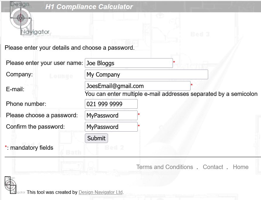
New to Design Navigator? |
| Terms and Conditions . Contact . Home |
 This tool was created by Design Navigator Ltd.


.cur)
The very first thing to check is whether the building is going to utilise energy from a network utility operator or uses any depletable energy sources. This is usually the case, but it would exclude for example a lifestyle home that has it's own solar power panels for electricity and uses firewood for space and water heating. But as soon as it would use LPG gas for example the exemption wouldn't apply because LPG is depletable.
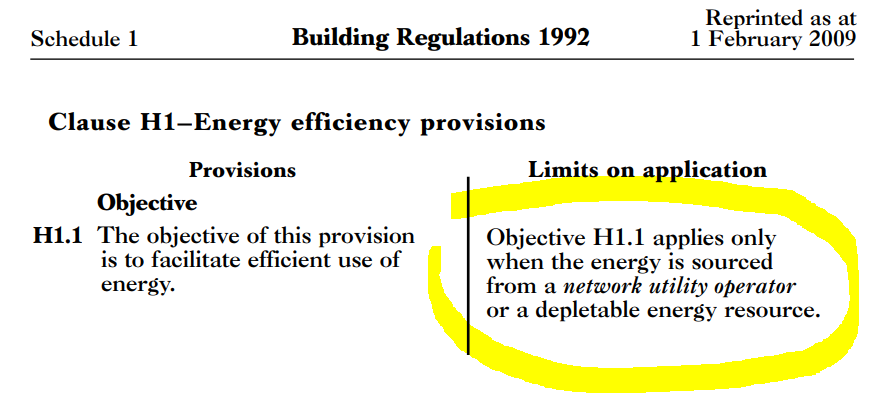
The next step to check is whether the building falls in one of the building classifications that do have to comply with the thermal requirements of H1.2(a). Specifically assembly service buildings, industrial buildings, outbuildings, and ancillary buildings do not have to comply with the thermal requirements of Clause H1. The screen shot below shows the relevant section in Clause H1.

A description of the classified uses with some examples is in Schedule 1 of the Building Code.
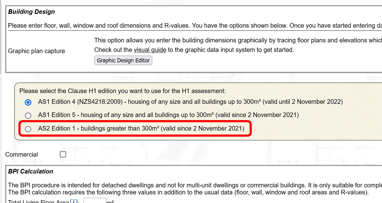
If the building does not fall into one of these groups then you have to comply with the thermal section of Clause H1. In that case the permitted compliance method depends on the building size and type.
| All housing, and all buildings up to 300m² |
Buildings larger than 300m² |
|---|---|
Typical examples:
|
Typical examples:
|
| until 2 November 2022: |
until 2 November 2022: |
|
|
| from 3 November 2022: |
from 3 November 2022: |
|
|
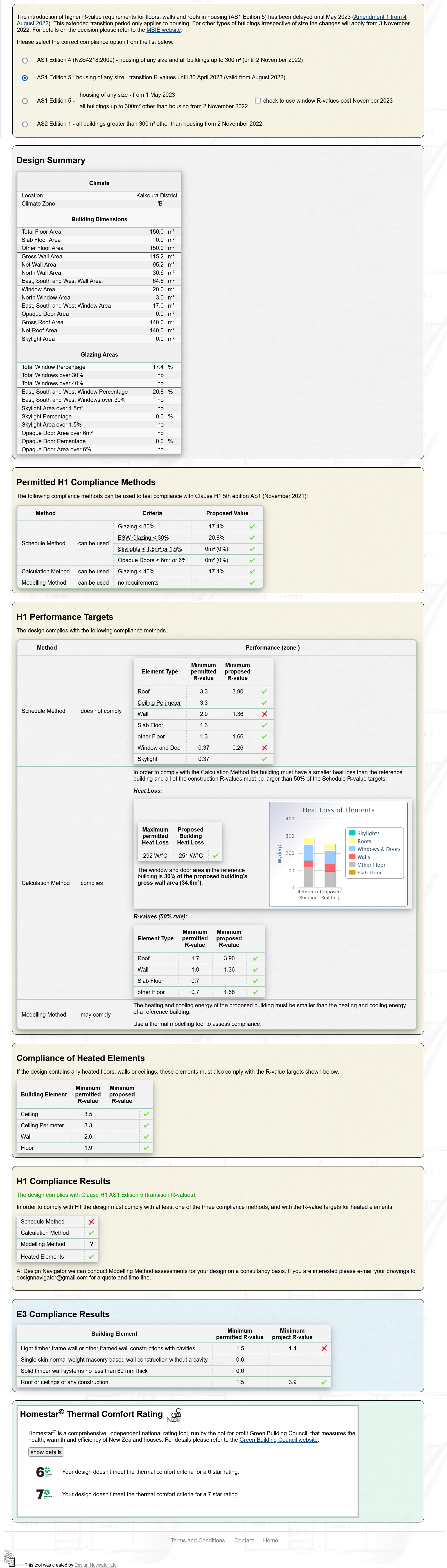
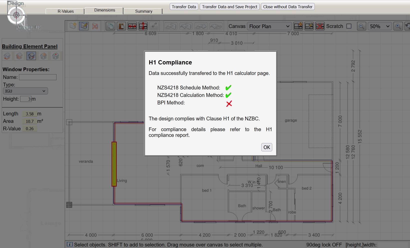
All of the Acceptable Solutions (AS1 Edition 4, AS1 Edition 5 and AS2 Edition 1) include a Schedule Method and a Calculation Method. The Schedule Method is a simple lookup table of R-values that your design has to meet. The Calculation Method allows some trade-offs between R-values in one element agains those in another. For example you can drop the roof insulation if you increase the wall insulation, etc. There are some prerequisites for using each of these methods and some additional requirement to meet the compliance requirements whch are specific to each version and edition of the Acceptable Solution. These conditions are all automatically checked within the Design Navigator Calculator. The Design Navigator Calculator also shows on its report pages why the design complies with a certain method or not.
One important thing to remember is that all of the Acceptable Solutions only assess the R-values of the building. They do not assess other thermal features such as solar exposure, thermal mass, internal air flows, etc. Although thermal insulation (R-values) are by far the most important factor for the thermal performance of a building looking at only the R-values can in some cases not give the full picture of a building's thermal performance and comfort.
The Verification Methods (VM1 Edition 4, VM1 Edition 5 and VM2 Edition 1) require a full scale thermal modelling of the building. Such a model simulates the building's heat flows and temperatures on an hour-by-hour scale for a typical climate year taking account the thermal insulation, but also factors such as solar gains (orientation of the building and window sizes), thermal mass, and it may even look at infiltration and ventilation effects. Such a model also looks at different thermal zones within a building. This allows the consideration of different comfort requirements throughtout building, i.e. a living room may be kept at 20degC whereas a bathroom at 16degC. These thermal simulations are reasonably complex and the Design Navigator calculator does therefore not include this assessment method. But I can undertake a Modelling Method assessment for you on a consultancy basis if you are interested.
The new Clause H1 Edition 5 unfortunately doesn't provide any clear guidance on alterations and additions. The Building Act says that if the building did not comply with the provisions of the building code immediately before the building work began, it has to “continue to comply at least to the same extent as it did then comply”. But in regards to energy efficiency performance it is not that clear what “the same extent” means.
If you only replace some building elements and don't change or add any additional elements then you can interpret that to say that you just must not reduce any R-values. But if it involves some additions to the building or other element alterations such as changing window sizes it becomes more complicated.
In those cases I recommend to use the approach that is described in NZS4218:2009 Appendix D. That suggests to assess the whole building, rather than just the new parts. But the trick is that for any existing unchanged parts of the building you can for calculation purposes assume that they have R-values meeting the Schedule Method targets (H1/AS1 Ed.5 Table 2.1.2.2B), irrespective of their actual R-values. Only for any new or changed elements (walls, windows, roofs, floor) you will have to calculate and use their actual construction R-values.
So for example if your existing building has R-1.7 walls, you can still enter R-2.0 for these existing walls in the DesNav calculator, as if they are meeting the current Schedule Method target. Only for those elements that are new or have been modified you enter their actual R-value.
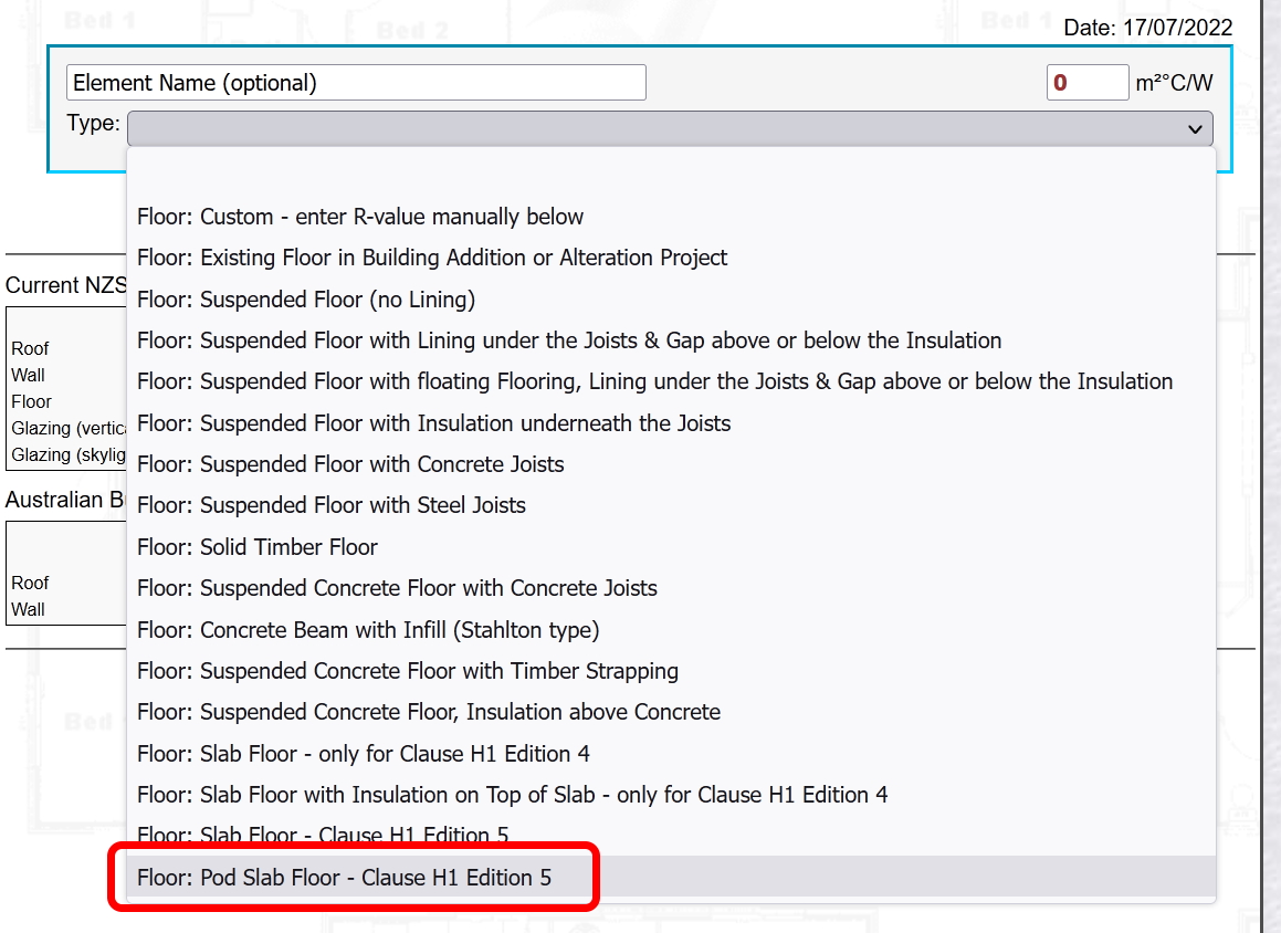
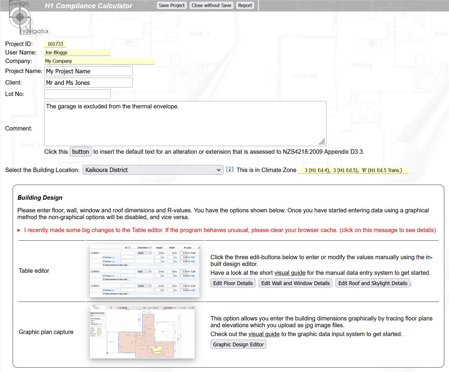
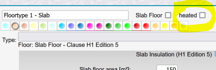
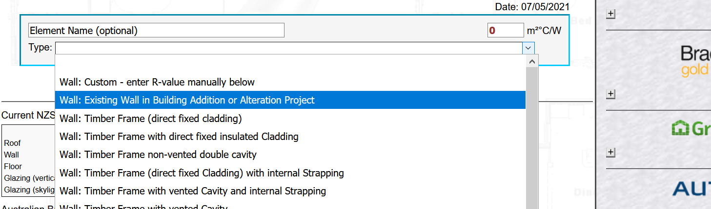
There is a DesNav construction R-value option for these unchanged existing elements. Make sure you select the option for the *current* H1 edition, i.e. the one you are checking for compliance for, rather than the H1 edition when those existing elements were built. So usually you should select one of the H1 Edition 5 options:
Internal elements between the new and the old part of the building are ignored just like normal internal walls, midfloor, etc.
You can only use those “default” R-values for existing parts that were residential and had to comply with H1 before. So if you are for example converting an existing garage into a living space you would need to use the actual garage R-values, meaning that you would probably have to insulate it, in case it wasn’t insulated before.
In AS1 Edition 4 you have some flexibility. It allow to show compliance for large building using either NZS4243 or NZS4218. NZS4218 is the method that is implemented in the Design Navigator for AS1 Edition 4 compliance.
That means that you can use the Design Navigator calculator to show compliance with Clause H1 AS1 Edition 4 also for a building larger than 300m². If the building fails to comply you can either increase the insulation levels to meet NZS4218 (using the Design Navigator calculator) or instead you check whether it complies with NZS4243 (which is not part of the DesNav calculator).
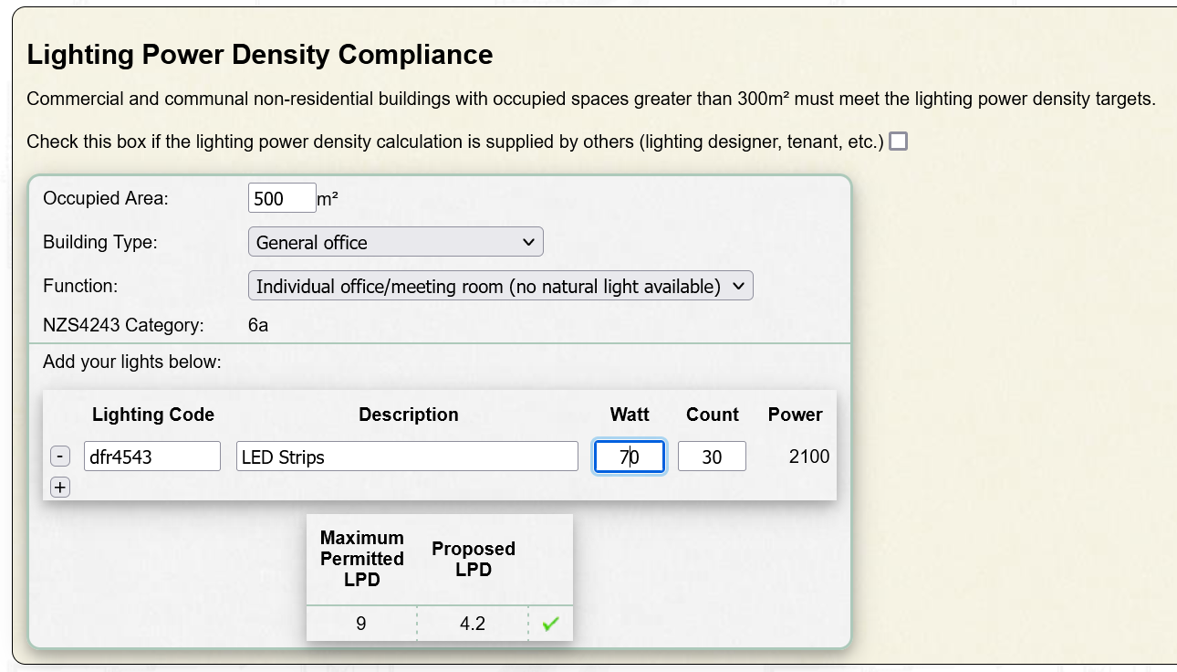
Note that for some large non-residential buildings you also need to show that the lighting power density complies with Clause H1. Usually your lighting consultant will be able to do these calculations for you.

Since November 2021 a new Acceptable Solution is available for buildings larger than 300m² that are not housing. This is "AS2 Edition1".
As with housing and buildings smaller than 300m² it includes a Schedule and a Calculation Method. The target R-values have been significantly increased compared to the NZS4243 which listed the target R-values for AS1 Edition 4.
The Design Navigator includes AS2 Edition 1, i.e. the Schedule and Calculation Methods for large buildings.
Simply enter your data as usual and select the AS2 Edition 1 assessment option.
The Design Navigator assessment also includes the Lighting Power Density calculation. You can use that in case your lighting designer does not provide the compliance statement for the lighting.
PS: I am also providing consultancy services to do H1 calculations for large commercial buildings. If you are interested you can send me the building plans to designnavigator@gmail.com and I can give you a quote.
You may have come across cases where an R-value has changed from the value that you previously calculated with the Design Navigator calculator.
There can be a few reasons for that:
Generally no.
When the Design Navigator program saves a project, it does not only save the selected detail name, but it also saves the corresponding R-values and also the other options that were avalable for that component. This makes it backward compatible. Assume for example that I change the name of a cladding product or remove it all together because it is no more on the market. If the calculations for your saved project would refer to the new Design Navigator version the calculation would crash because it couldn't find the product anymore. Therefore all the products that were available for your selected construction detail are saved and restored when you re-open the project.
The other reason is that it would be quite confusing if you would create an H1 report for a project, and when you open the project again some time later the new R-values - and possibly even compliance results - would be different from the ones in the report that you created earlier.
There can of course be cases where you want to use the new product or an updated R-value for that product. In that case you will have to create a new construction R-value. Then simply select the same details as for your old construction R-value calculation in your project. Because you created a new construction the program will in that case use the current product names, R-values and calculation methods.
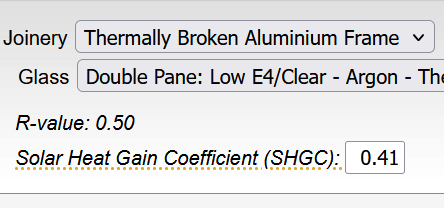
F.1.2.2 says:

That's a recommendation only, and not mandatory.
But there are a few implications on how to calculate the slab R-value:
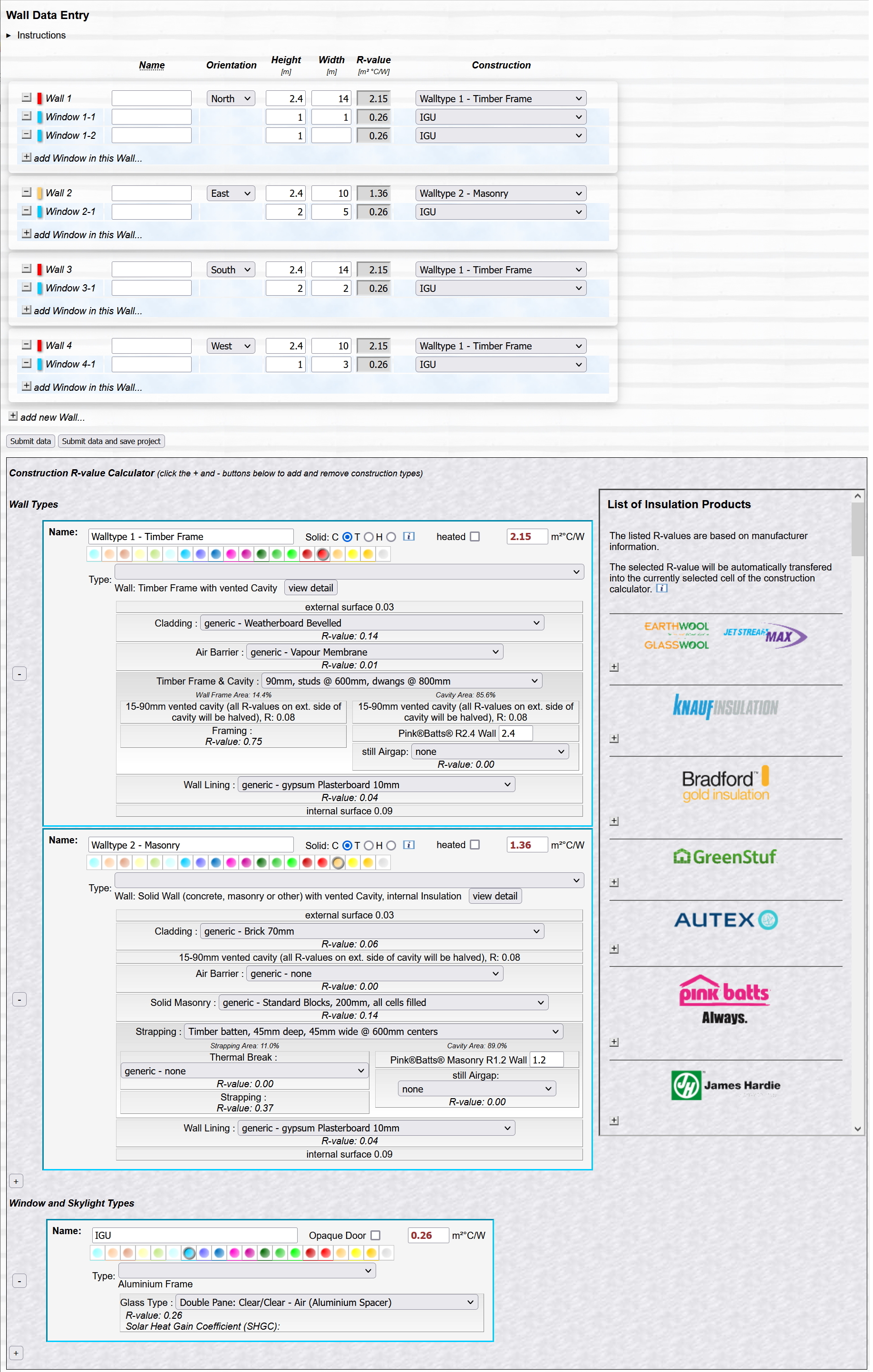
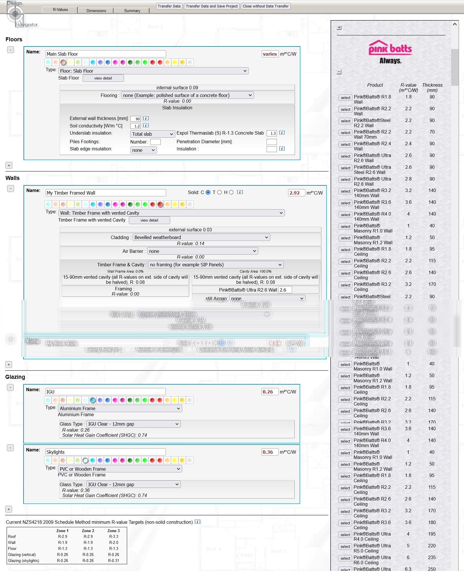
The Design Navigator calculator calculates assembly construction R-values according to the method described in NZS4214:2006 as required in Clause H1 of the New Zealand Building Code.
The calculation assesses the overall construction R-value based on a series of layers of materials that are placed behind each other. If these layers are all homogenious the R-values of the individual layers can simply be added together. But if the assembly contains non-homogenious layers, such as a framing/insulation layer, then the calculations become more complex. NZS4214:2006 describes how to undertake these calculations.
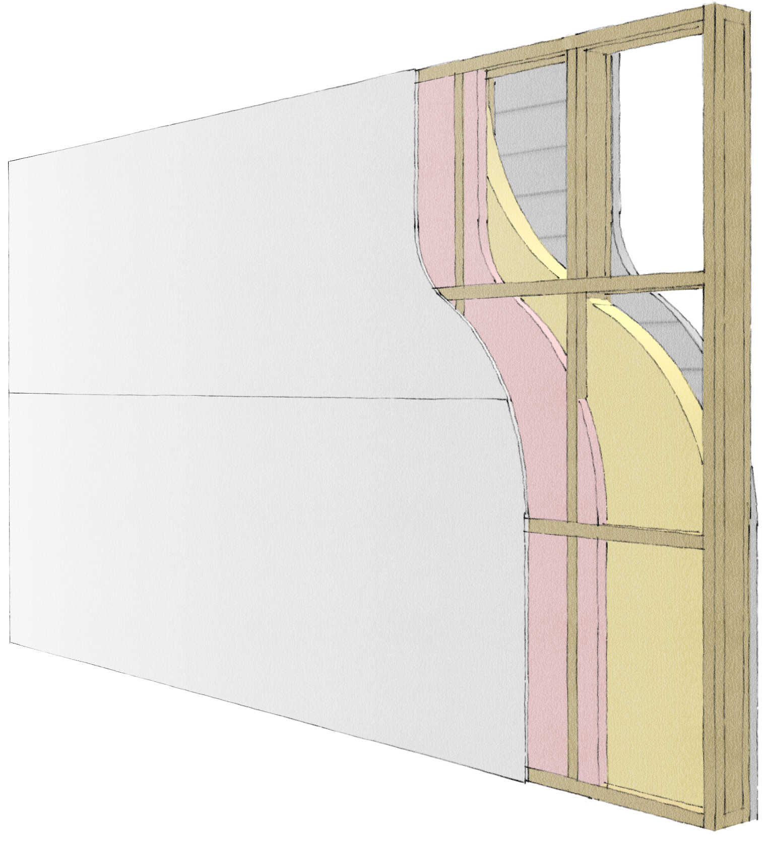
The method in the Standard is generally referred to as the "isothermal planes" method. The term refers to the assumption that the planes between adjacent layers of material are always at a uniform temperature as indicated in the sketch below (Figure 1).
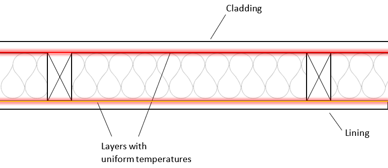
This assumption is generally valid because most layers, such as the lining and the cladding in the example above, have low R-values. This means that heat will easily spread throughout the whole layer giving it a fairly uniform temperature. There are of course small temperature variations where the framing meets the lining and the cladding, but these variations can generally be ignored because of the small impact that these layers (lining and cladding) have on the overall construction R-value.
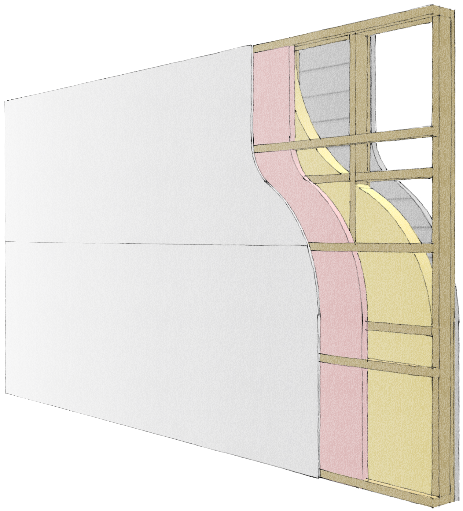
However, there are certain assemblies where this assumption is not correct and the impact on the assembly construction R-value becomes significant. Specifically where two insulation layers are in direct contact the temperature fluctuations that are caused by non-homogenious layers (such as the framing/insulation layer) will have a large impact on the construction R-value. The sketch in figure 2 illustrates this.
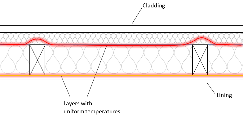
In this case the high R-value of the second insulation layer does not allow heat to disperse quickly across the layer. So the temperature in the plane between the original framing/insulation layer and that second insulation layer is not uniform. The reason why this has a larger effect on the overall construction R-value is that the layer containing these temperature disturbances is an insulation layer and therefore the influence on the overall R-value is more significant than in a lining or cladding layer which has a low R-values in the first place.
The isothermal planes method basically assumes that each layer is thermally isolated from the next, and therefore its R-value can be calculated without reference to any adjacent layers. But there are cases where this assumption does lead to obviously incorrect results. There are two such cases which you may have noticed at some stage already when using the Design Navigator R-value calculator:
|
|
The upcoming changes of Clause H1 require much higher insulation levels. One practical solution are the addition of counter battens to wall and roof framing. This detail is therefore likely to become much more common and it is therefore important to have a more realistic calculation procedure for these "double insulation layer" details.
I have therefore updated the calculations for these types of scenarios. In simplified terms I have changed the calculations so that these double layers are being treated as one layer consisting of multiple sections with combinations of timber/timber, timber/insulation and insulation/insulation. By doing this the construction R-values of these details have improved and are more realistic.
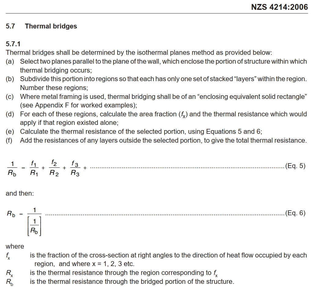
This approach is valid and in line with the requirements of Clause H1 because NZS4214:2006 allows some flexibility in terms of how layers should be defined in the isothermal planes calculation method.
Item (a) in the instructions for isothermal planes calculations in NZS4214:2006 states that the two planes shall "enclose" the portion of the structure including the thermal bridging. This can be interpreted as meaning that multiple adjacent layers with thermal bridging can either be treated as separate bridged layers or as one combined bridged layer.
Research conducted by BRANZ and published in a paper at the ASHRAE Annual Conference in 1995 shows that this modified isothermal planes method has an excellent correlation with a large variety of construction details that were measured in the lab. Although this paper is several decades old no other reseach has shown since that there is a more accurate approach to achieve better correlations with measured data. (Harry Trethowen, SD-95-05-1 -- Validating the Isothermal Planes Method for R-Value Predictions, Symposium, ASHRAE Trans. 1995, Vol.101, Part 2).
The changed approach to calculating these double insulation layers will increase the R-value of the assembly compared to the previous calculation method and be more in line with real measurement results.
This modified calculation is only applied to Design Navigator R-value calculations conducted from now on. If you calculated an R-value for a double insulation layer detail previously the old method is applied since the underlying format of the data that you entered at that time is preserved in your saved projects. If you want to update an old value please create a new construction detail with identical details.
No. Once you have paid for a report you can still make changes to the project and download a new copy of the report free of charge. Just follow the usual process. On the reports page the system will only ask for your e-mail address and not for any payment.
Just make sure that you open the original project and don't create a copy of the project. If you create a copy of the project this will be treated like a new project and you would therefore have to pay for the report of the copied project.
No. Reports for projects that were created before the 19th of February 2015 remain free of charge.
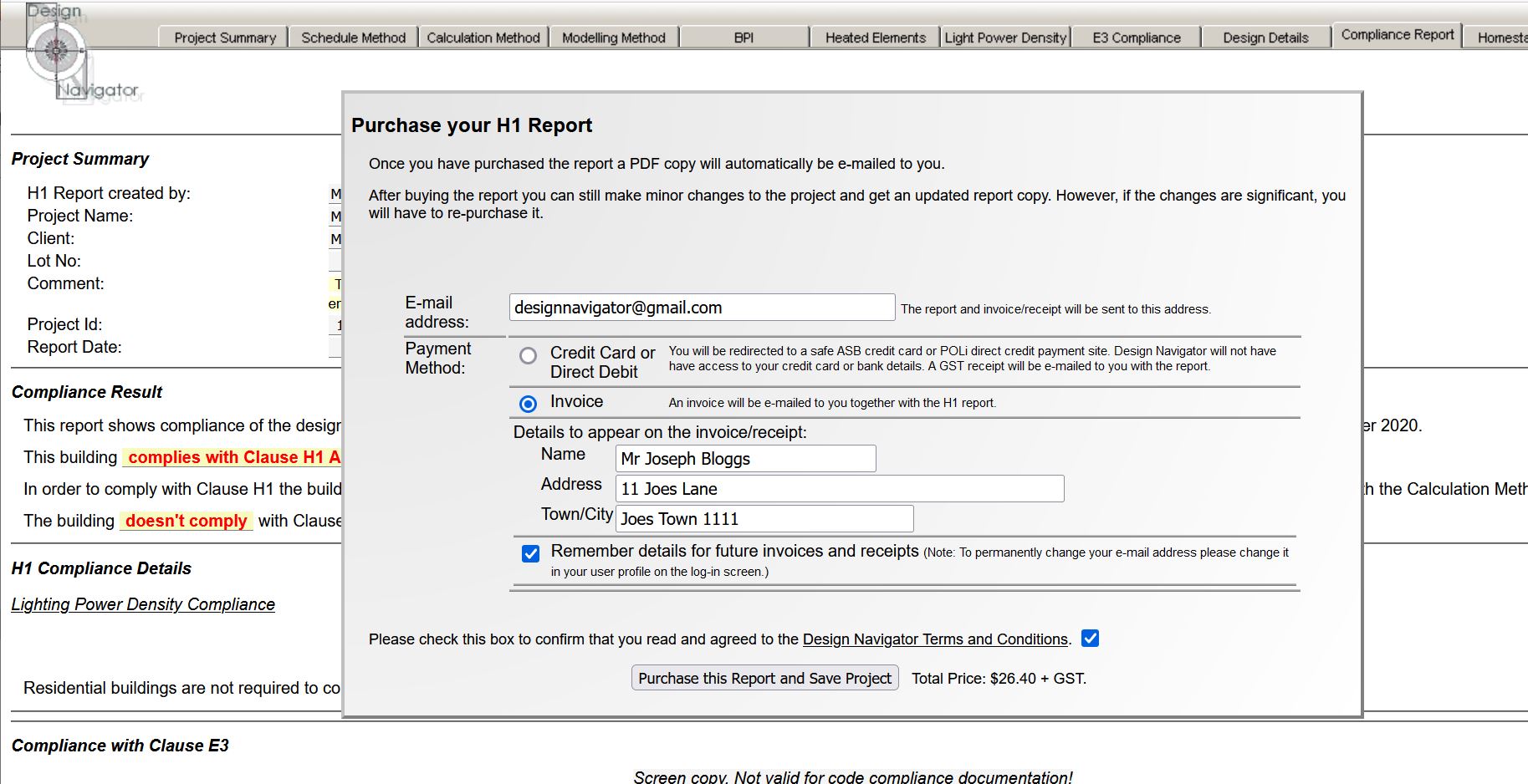
The payment system is set up so that when you open the report page you have two choices, either pay by credit card or be invoiced.
If you select credit card the website redirects to a separate ASB website where you enter all the credit card details. Once that is done it returns to the DesNav page and e-mails you the report and a receipt. Design Navigator does at no point have access to any of your credit card details.
If you choose the invoice option the DesNav website will automatically send you the H1 report and together with it an invoice.
There is also a monthly invoicing system available. This system collates all invoices during each month. The system can be particularly useful for larger design firms where there are multiple users, but the invoices are paid centrally by administration or accounting staff because there can be multiple users assigned to such a monthly invoicing system. Please let me know if you would like to have an account set up for this.